


Study of Residual Stress Distribution of Large Ring-type Dissimilar Metal Weld in Reactor Pressure Vessel
-
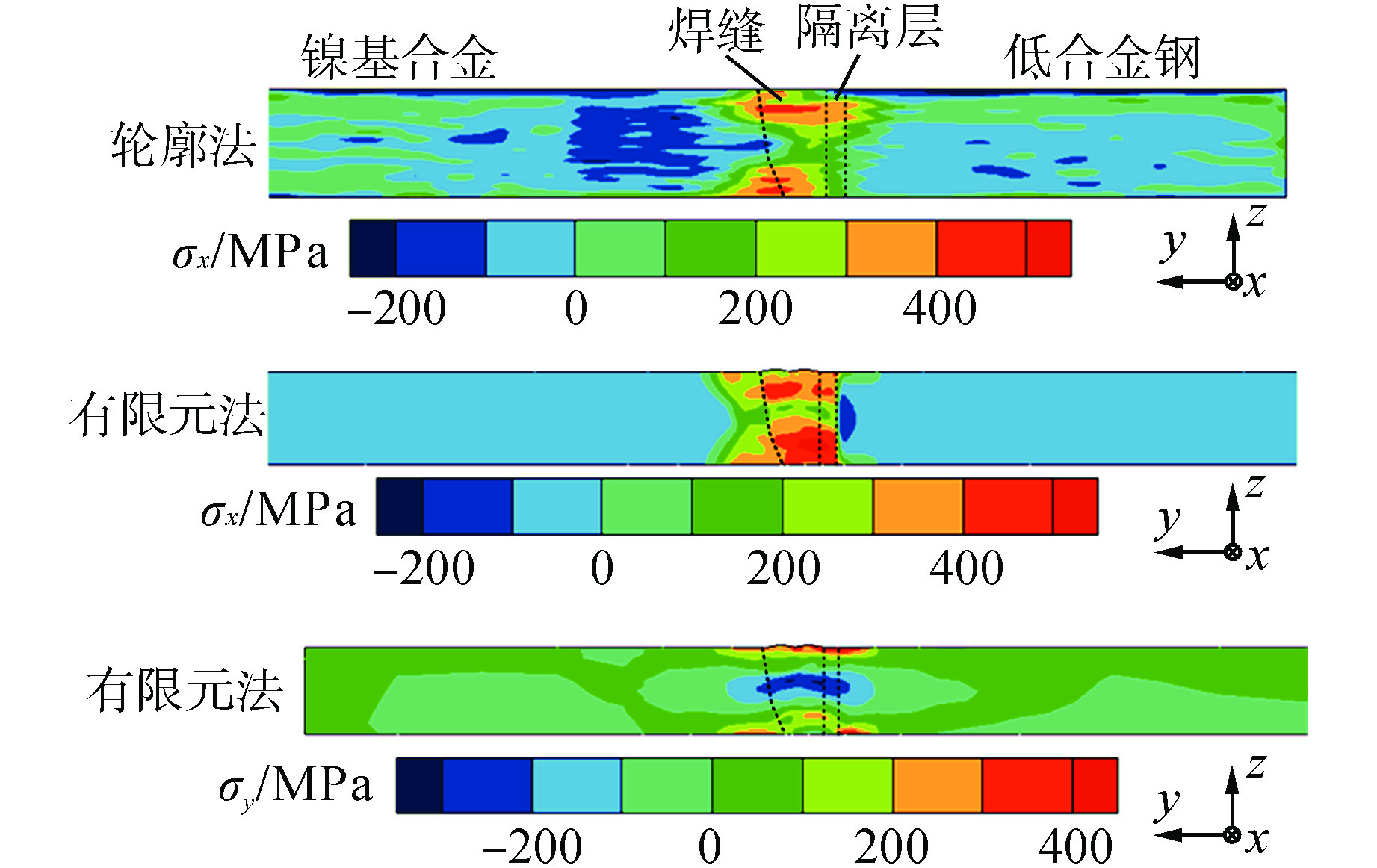
摘要: 获得反应堆压力容器内部大尺寸环形异种金属焊缝残余应力分布可为反应堆压力容器结构设计和制造工艺优化提供指导,通过设计和制造能够代表产品焊接结构形式的镍基合金和低合金钢异种金属焊接结构模拟件,采用轮廓法测试焊接结构模拟件内部纵向残余应力,采用有限元法模拟计算焊接结构模拟件横向和纵向残余应力,获得了整个异种金属焊接接头残余应力分布特征。结果表明:焊缝区域内部纵向残余应力为拉伸应力,峰值应力达到500 MPa左右,并且表层应力大于内部应力,峰值应力出现在距下表面3 mm和24 mm位置;横向残余应力在焊缝区域从上表面到下表面的分布为拉应力-压应力-拉应力,压缩横向残余应力峰值达到−300 MPa,出现在距下表面约18 mm位置。本文研究可为焊接结构设计提供理论指导。Abstract: To obtain the residual stress distribution of the large ring-type dissimilar metal weld in the reactor pressure vessel(RPV), and guide the structural design and manufacturing process optimization of the reactor pressure vessel, the dissimilar metal welding structure simulators of nickel base alloy and low alloy steel, which can represent the welding structure form of products, are designed and manufactured. The longitudinal residual stress in the welding structure simulators is tested by contour method, and the transverse and longitudinal residual stress of the welding structure simulators are simulated and calculated by finite element method. The residual stress distribution characteristics of the whole dissimilar metal welding joint are obtained. The results show that the longitudinal residual stress in the weld area is tensile stress, the peak stress reaches about 500 MPa, and the surface stress is greater than the internal stress, and the peak stress occurs at 3 mm and 24 mm from the lower surface; The distribution trend of transverse residual stress in the weld area from the upper surface to the lower surface is tensile stress - compressive Stress - tensile stress. The peak value of compressive transverse residual stress reaches −300 MPa and appears about 18 mm away from the lower surface. The research in this paper can provide theoretical guidance for the design of welding structures.
-
Key words:
- Reactor pressure vessel(RPV) /
- Dissimilar metal /
- Welding residual stress /
- Test /
- Numerical simulation
-

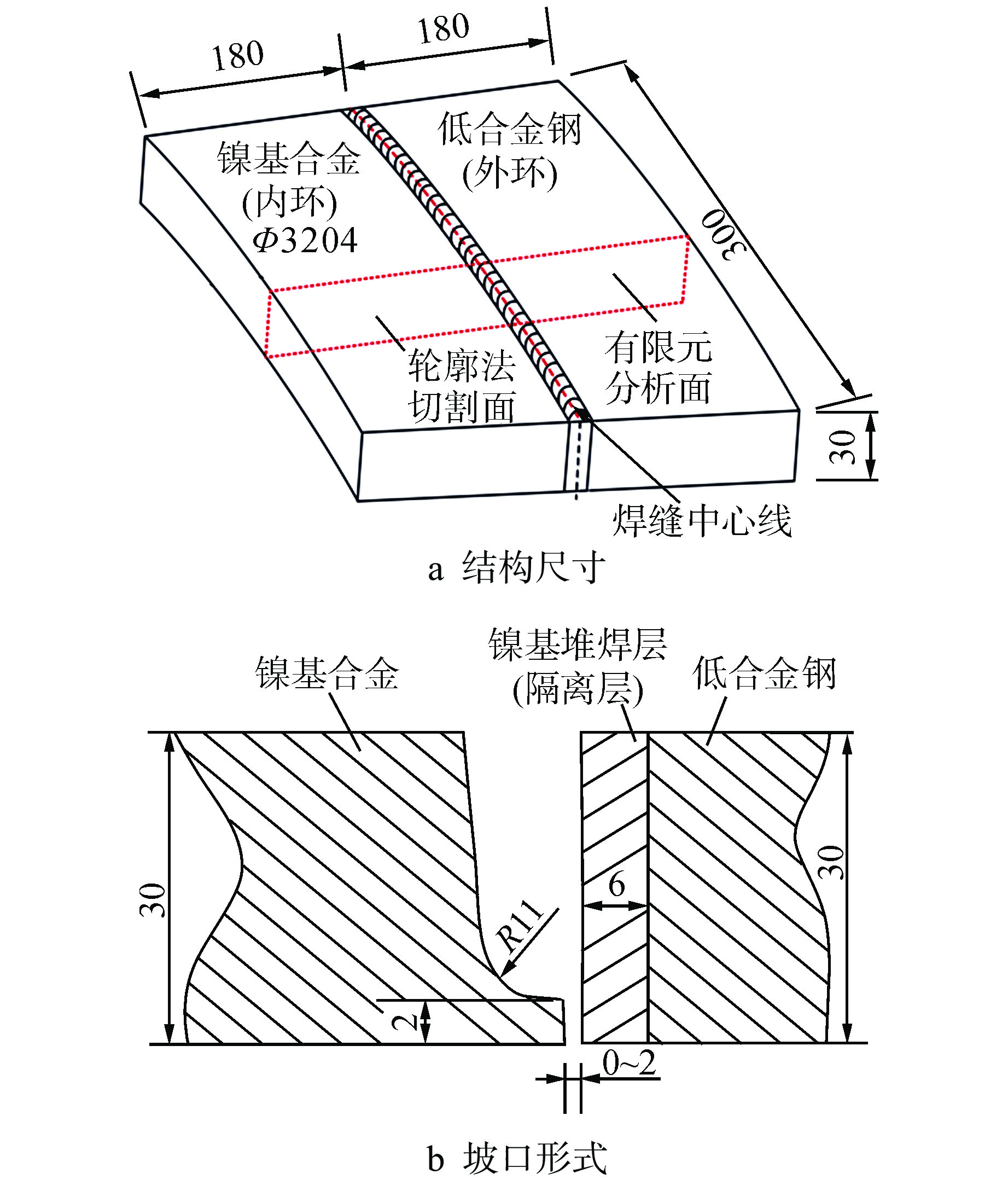
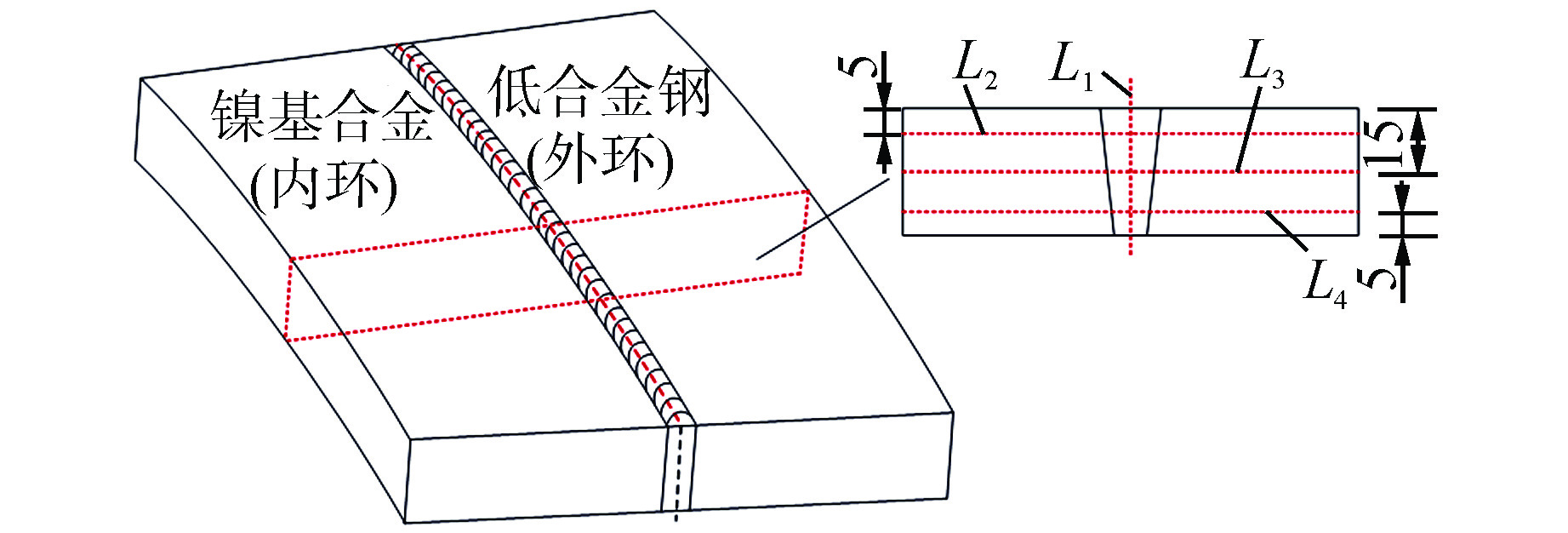
图 2 焊接结构模拟件示意图 单位:mm
Ф—直径;R—半径
Figure 2. Schematic Diagram of Welding Structure Simulator

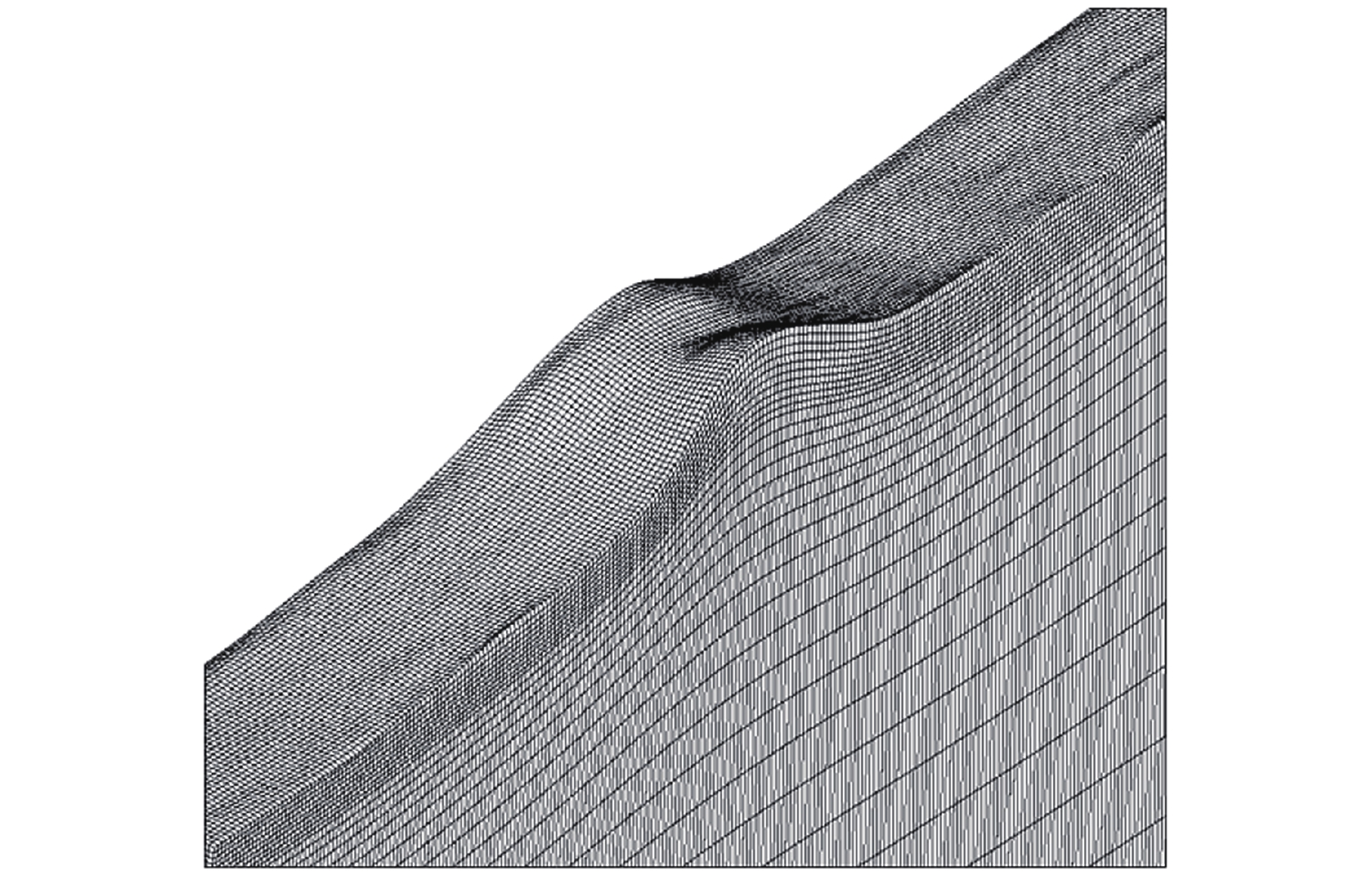
图 5 加载边界条件后的变形有限元模型
Figure 5. Deformed Finite Element Model after Applying Boundary Conditions

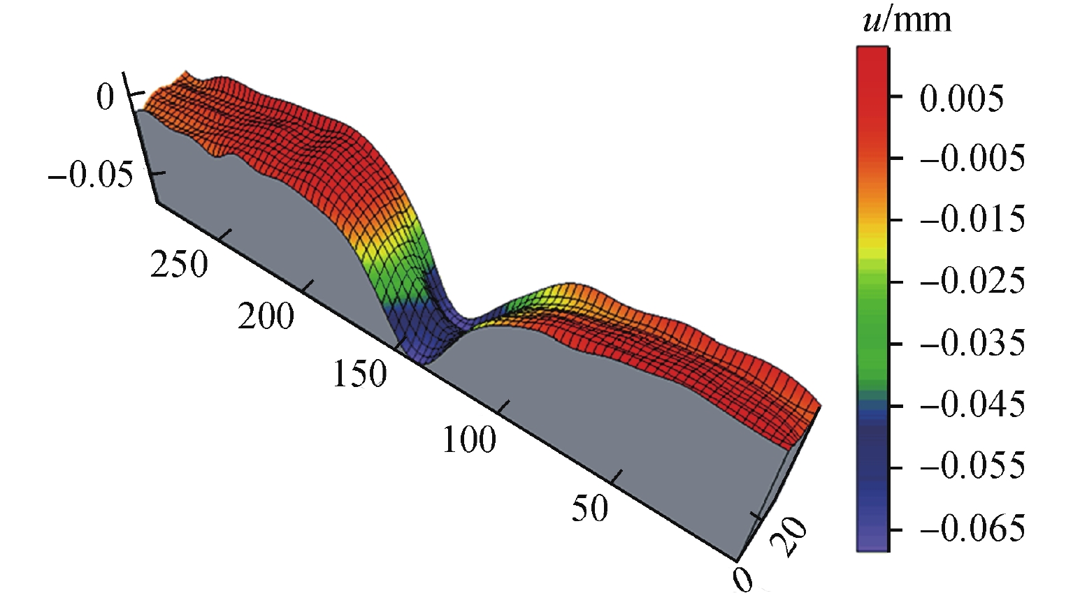
图 7 应力测试和模拟计算的应力分布图
Figure 7. Stress Distribution Diagram of Stress Test and Simulation Calculation

图 9 应力评价线上的应力分布
σ—残余应力;t—距下表面的距离;d—距焊缝中心的距离
Figure 9. Stress Distributions along Evaluation Lines
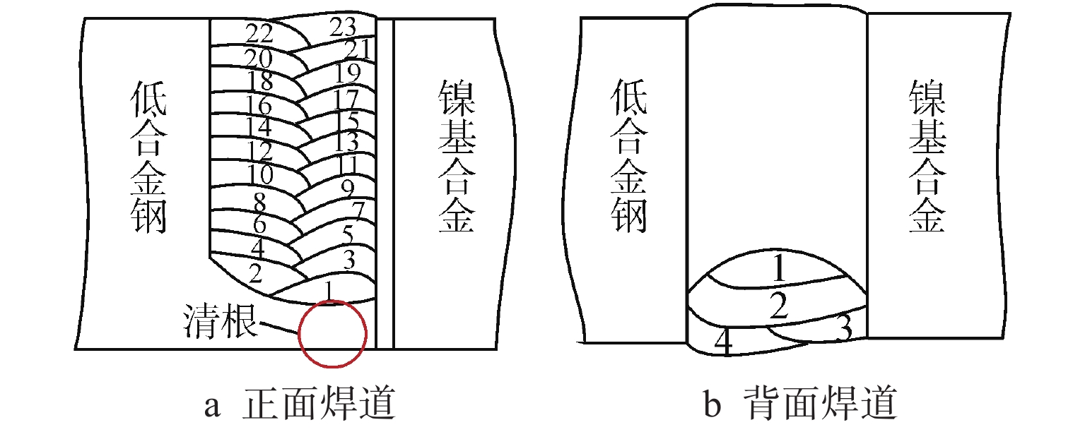
表 1 焊接结构模拟件焊接工艺参数
Table 1. Welding Process Parameters of Welding Structure Simulator
焊接部位 焊接电压/V 焊接电流/A 焊接速度/(mm·min−1) 根部焊缝 26~28 119~123 190 填充焊缝 32~35 125~126 175 盖面焊缝 32~35 125~126 310  下载: 导出CSV
表 2 16MnD5低合金钢材料性能
Table 2. Material Properties of 16MnD5 Low Alloy Steel
T/℃ cp/
(J·kg−1·℃−1)λ/
(W·m−1·℃−1)E/
GPaRp0.2/
MPaα/
10−6℃−120 430 38.4 212 512 7.83 100 487 41.1 207.2 − 7.81 200 526 40.9 201.3 − 7.78 300 560 39.5 194.7 442 7.75 400 605 38.3 187.1 397 7.72 600 746 34.8 167.9 296 7.65 700 − − − 126 − 760 1510 59.0 − − 7.66 800 873 36.7 142.4 64 7.64 900 633 28.4 126.6 − 7.59 982 641 28.3 108.4 − 7.55 1200 − 30.9 61.8 10 7.55 1327 735 32.4 32.5 − 7.55 1400 835 33.8 2.2 − 7.55 注:T—温度;cp—定压比热容;λ—热传导系数;E—弹性模量;Rp0.2—材料屈服强度;α—热膨胀系数;“−”—无数据,下同
下载: 导出CSV
表 3 镍基合金材料性能
Table 3. Material Properties of Nickel-based Alloy
T/℃ cp/
(J·kg−1·℃−1)λ/
(W·m−1·℃−1)E/
GPaRp0.2母材/
MPaRp0.2焊缝/
MPaα/
10−6℃−120 450 12.0 215 331 460 14.1 100 470 14.0 208 − 260 14.1 200 500 16.0 201 − − 14.3 300 525 18.0 195 275 − 14.5 400 550 19.5 189 − − 14.8 600 605 23.3 175 163 200 15.7 700 630 25.0 167 − 16.2 800 655 26.6 160 93 − 16.6 900 685 28.2 152 − 17.0 1000 715 29.7 143 50 50 17.3 1100 740 30.3 − − − − 1400 − − − 10 10 −
下载: 导出CSV
-
[1] RUDLAND D, CHEN Y, ZHANG T, et al. Comparison of welding residual stress solutions for control rod drive mechanism nozzles[C]//Proceeding of ASME 2007 Pressure Vessels and Piping Conference. San Antonio, Texas, USA: ASME, 2007: 997-1011. [2] 林炳炽,徐晓,金挺,等. 贯穿件J形坡口焊接残余应力分析[J]. 核动力工程,2020, 41(1): 70-74. [3] 杨敏,罗英,付强,等. 基于模拟件-产品件方法研究反应堆压力容器顶盖与多个CRDM管座焊接残余应力[J]. 核动力工程,2015, 36(6): 75-78. [4] PRIME M B. Cross-sectional mapping of residual stresses by measuring the surface contour after a cut[J]. Journal of Engineering Materials and Technology, 2001, 123(2): 162-168. doi: 10.1115/1.1345526 [5] HOSSEINZADEH F, BOUCHARD P J. Mapping multiple components of the residual stress tensor in a large P91 steel pipe girth weld using a single contour cut[J]. Experimental Mechanics, 2013, 53(2): 171-181. doi: 10.1007/s11340-012-9627-z [6] 刘川,庄栋. 基于轮廓法测试焊接件内部残余应力[J]. 机械工程学报,2012, 48(8): 54-59. [7] ZHANG Y, GANGULY S, EDWARDS L, et al. Cross-sectional mapping of residual stresses in a VPPA weld using the contour method[J]. Acta Materialia, 2004, 52(17): 5225-5232. doi: 10.1016/j.actamat.2004.07.045 [8] RICHTER-TRUMMER V, SUZANO E, BELTRÃO M, et al. Influence of the FSW clamping force on the final distortion and residual stress field[J]. Materials Science and Engineering:A, 2012, 538: 81-88. doi: 10.1016/j.msea.2012.01.016 [9] 迟露鑫,麻永林,邢淑清,等. 核电SA508-3钢厚壁圆筒纵向焊接残余应力分析[J]. 焊接学报,2012, 33(6): 59-62,67. [10] SMC. Special Metals[EB/OL].(2009-10-09)[2021-09-01]. https://www.specialmetals.com. [11] VDM Metals. VDM® alloy 690 nicrofer 6030: material data sheet No. 4038[R]. Madrid: A Company of ACERINOX, 2021. [12] CHO J R, LEE B Y, MOON Y H, et al. Investigation of residual stress and post weld heat treatment of multi-pass welds by finite element method and experiments[J]. Journal of Materials Processing Technology, 2004, 155-156: 1690-1695. doi: 10.1016/j.jmatprotec.2004.04.325 -


 点击查看大图
计量
- 文章访问数: 152
- HTML全文浏览量: 27
- PDF下载量: 34
- 被引次数: 0
