Research on Two-Dimensional Ultrasonic Contour Imaging Algorithm for Weld between Nozzle to Shell of Reactor Pressure Vessel
-
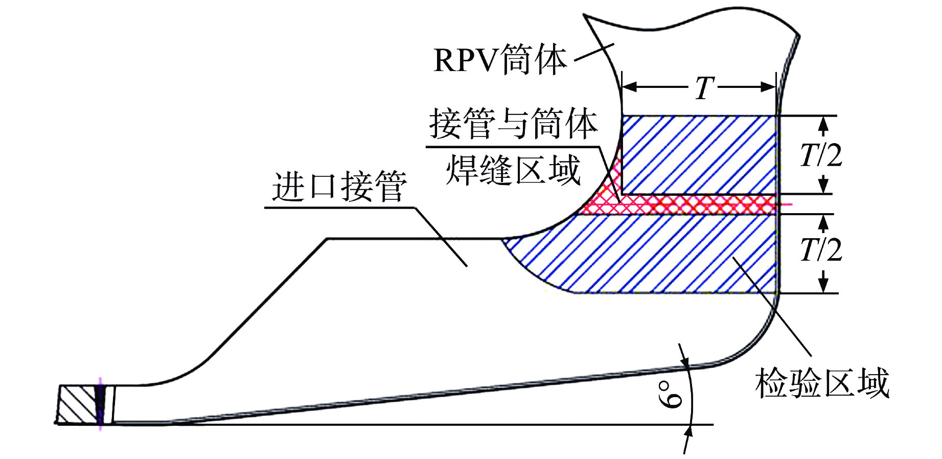
摘要: 核电厂复杂几何形状焊缝的超声信号位置直观显示对缺陷判断具有重要参考价值。核电厂反应堆压力容器(RPV)接管内表面通常带有一定的倾斜角度,采用传统的矩形B扫描成像算法,接管与筒体焊缝超声B/C扫描成像显示存在显示不直观、缺陷定位不准确的突出问题。本文提出了直线与直线、圆弧与椭圆弧通过圆弧相切连接的算法,利用绘制直线、弧的库函数实现轮廓的绘制并将超声信号显示在轮廓之中,形成了带轮廓的B扫描图像。通过计算在轮廓中穿过闸门线的A扫描信号的阈值,形成马鞍面形状的C扫描图像。核电厂RPV接管与筒体焊缝现场超声扫查数据验证了该算法的有效性和实用性。Abstract: The visual display of ultrasonic signal position of complex geometric welds in nuclear power plants has important reference value for defect judgment. The inner surface of the nozzle of reactor pressure vessel (RPV) in nuclear power plant usually has a certain inclination angle. By using the traditional rectangular B-scan imaging algorithm, there are some outstanding problems in ultrasonic B/C scan imaging of welds between nozzle and shell, such as unintuitive display and inaccurate defect location. In this paper, the algorithm of tangent connection between straight line and straight line, arc and elliptical arc through arc is proposed. The library function of drawing straight line and arc is used to draw the contour, and the ultrasonic signal is displayed in the contour to form a B-scan image with contour. A saddle shaped C-scan image is formed by calculating the threshold of the A-scan signal passing through the gate line in the contour. The validity and practicability of the algorithm are verified by the on-site ultrasonic scanning data of the RPV nozzle and shell weld in the nuclear power plant.
-
Key words:
- Welds between nozzle and shell /
- Ultrasonic contour /
- Algorithm /
- Saddle surface C scan
-
表 1 检验探头清单
Table 1. Inspection Probe List
序号 频率/ MHz 折射角 晶片尺寸/mm×mm 1 2.25 6° 25×32 2 2.25 24° 25×32 3 2.25 36° 25×32 4 2.25 39° 25×32 5 2.25 51° 25×32 表 2 关键点定义与含义
Table 2. Definition and Meaning of Key Points
序号 参数 含义 1 Ta 探头倾角,GP与FG的夹角(锐角) 2 Si MQ与FG的相连圆弧半径 3 So O2C、O2D的值,焊层连接圆弧半径 4 Rt RPV筒体厚度 5 Ct 堆焊层厚度,E′E″的距离 6 Pi 突出部分内半径数值 7 Ba BB′的倾斜角度(锐角) 8 Le AB″直线距离 9 Nr 接管内半径,FG到支管中心线的距离 10 Bo BC到接管中心线的距离 11 Po AB″到接管中心线的距离 12 Sv 检验区域上边界到接管中心线的距离 13 Ev 检验区域下边界到接管中心线的距离 14 Tp M点到接管中心线的距离 15 St 接管斜坡起始位置到容器中心线的距离 16 Vr RPV内半径(到堆焊层) 17 Pr 接管突出部分圆弧半径 18 Eb B点到容器中心线的距离 19 Et F点到容器中心线的距离 20 Er O1B′直线距离 21 Pa 声线角度 注:表中线段表示详见图4所示。 表 3 RPV接管与筒体输入参数列表
Table 3. Input Parameter List of RPV Nozzle and Shell
参数 数值 参数 数值 Ta 6.0° Si 5.38″ So 5.38″ Rt 11.50″ Ct 0.32″ Pi 0.35″ Ba 30.0° Le 10.00″ Nr 13.74″ Bo 27.00″ Po 16.23″ Sv 27.25″ Ev 36.38″ Tp 22.45″ St 122.31″ Vr 85.44″ Pr 84.44″ Eb 10.75″ Et 125.68″ Er 3.75″ Pa 58.0° / / 注:1″=2.54 cm -
[1] 张运平,张志鹏,周帆,等. 反应堆压力容器接管与筒体连接焊缝相控阵超声检验技术研究[J]. 科技视界,2019(3): 205-206. [2] 余成,刘乾. 核岛反应堆压力容器大直径接管马鞍形焊缝焊接工艺[J]. 电焊机,2016, 46(11): 38-44. [3] 唐亮,张进,邓小云. 核电厂BOSS焊缝的相控阵超声检测[J]. 无损检测,2019, 41(6): 46-50. [4] 顾明帮. 核电厂BOSS头焊缝的无损检测[J]. 智能城市,2019, 5(21): 186-187. [5] 鲁万乾,刘聪. 核电厂反应堆压力容器接管焊缝缺陷处理[J]. 电工技术,2017, 12(12): 147-150,152. doi: 10.3969/j.issn.1002-1388.2017.12.065 [6] 压力容器委员会. ASME锅炉及压力容器规范Ⅺ卷[M]. 2000补遗, 北京: 中国石化出版社, 1998. -


 下载:
下载:


