Design and Performance Investigation of Supercritical Carbon Dioxide Ejector
-
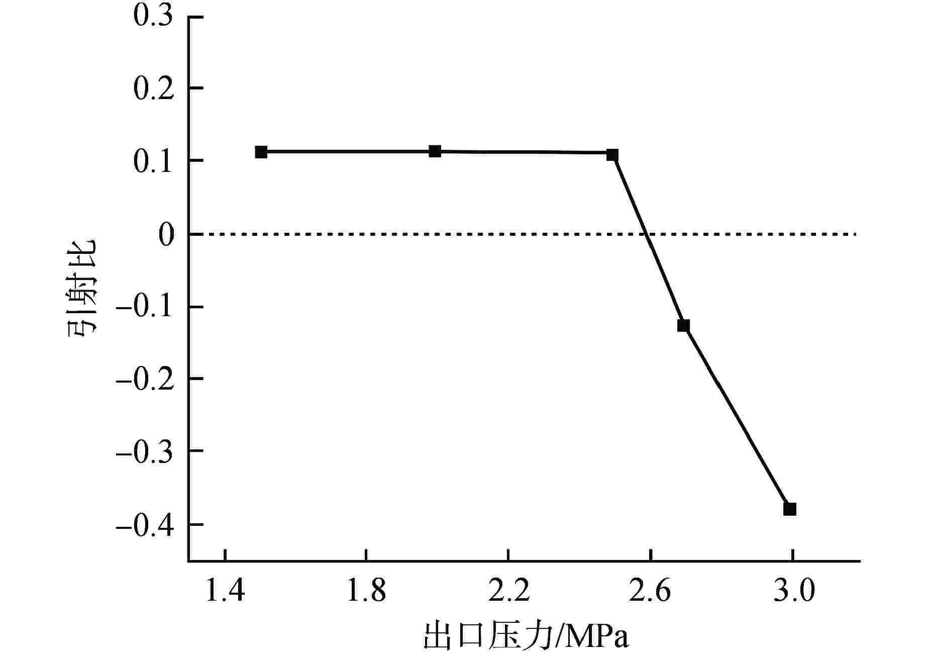
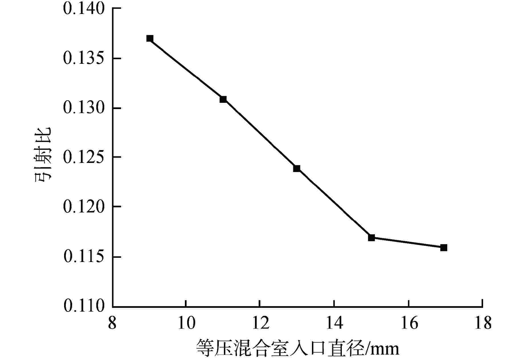
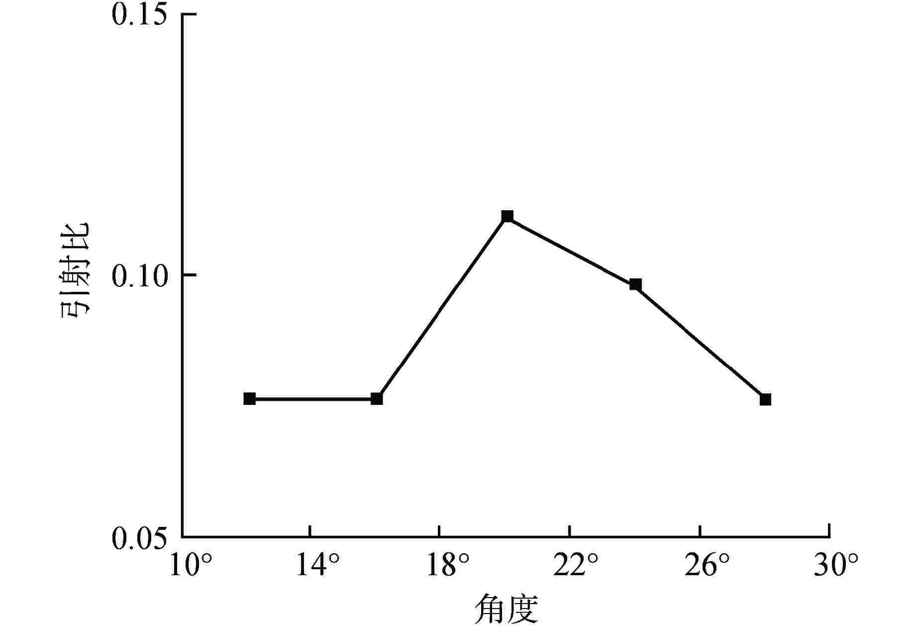
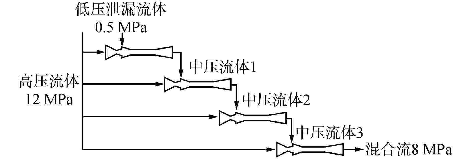
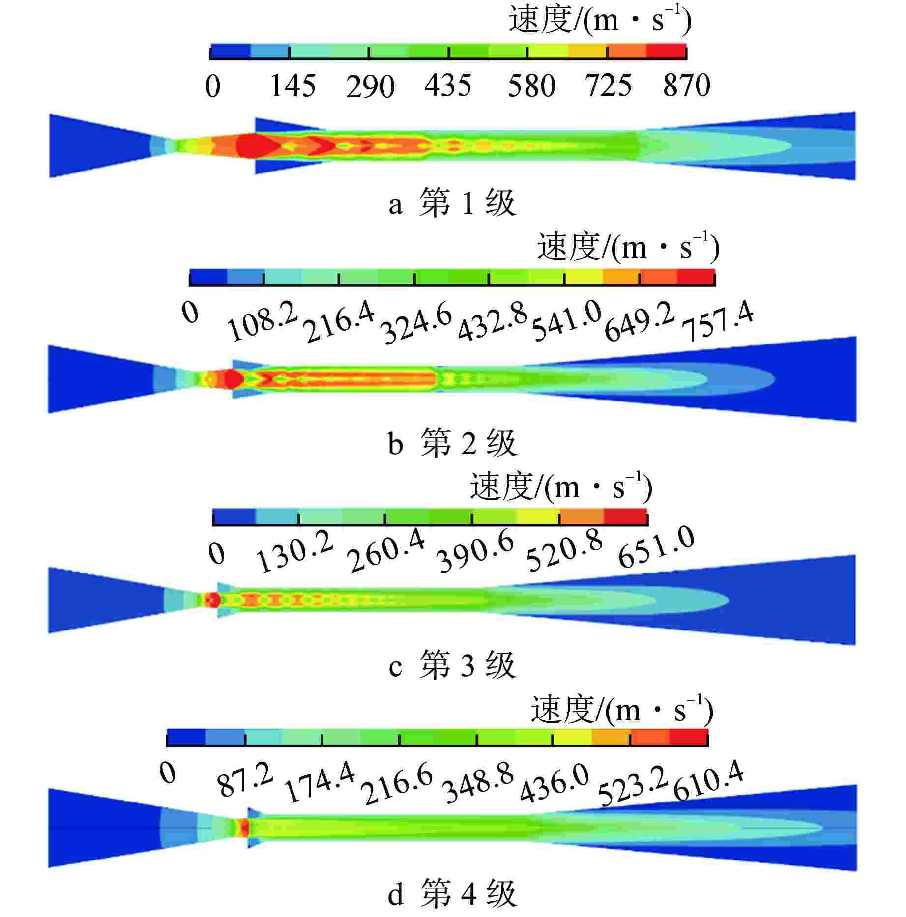
摘要: 在不额外消耗机械功的条件下,为了尽可能消除超临界二氧化碳涡轮系统中产生的泄漏气体对循环稳定性的负面影响,本文基于等压混合理论和双壅塞临界状态设计了可将泄露气体加压输送回循环的喷射器结构,使用计算流体力学软件Fluent对该模型进行数值模拟,分析喷射器的性能,探究尺寸参数对喷射器性能的影响。结果表明,四级串联的喷射器能依次将0.5 MPa泄漏气体加压至2.0、4.4、6.0、8.0 MPa,实现泄漏气体的回收利用;喷射器背压小于临界压力时,引射比不受背压影响,喷射器背压大于临界压力时,引射比随背压的增大而急剧减小;引射比随入口截面的减小而增大,随喷嘴收缩角的增大先增大后减小,在收缩角为20°时,引射比达到最大。Abstract: In order to minimize the negative impact of leakage gas produced on the stability of the supercritical carbon dioxide cycle without additional mechanical work consumption, an ejector that can pressurize and transport the leakage gas back to the cycle was designed in this paper based on the constant pressure mixing theory and the double choked critical state. The computational fluid dynamics software Fluent was used to simulate the model numerically, analyze the performance of the ejector, and investigate the effect of size parameters on the performance. The results show that the four-stage ejector can sequentially pressurize the 0.5 MPa leakage gas to 2.0, 4.4, 6.0 and 8.0 MPa, realizing the recovery and utilization of the leaked gas. The entrainment ratio is not affected by the back pressure when the back pressure is less than the critical pressure. The entrainment ratio decreases sharply with the increase of the back pressure when the back pressure is greater than the critical pressure. The entrainment ratio increases with the diminution of the inlet area. The entrainment ratio increases first and then decreases with the increase of the contraction angle of the nozzle, and reaches maximum while the contraction angle is 20°.
-
Key words:
- Supercritical carbon dioxide /
- Leaked gas /
- Multi-stage ejector /
- Structure optimization
-
表 1 流体初始参数
Table 1. Initial Parameters of Fluids
工质 压力/MPa 温度/K 质量流量/(kg·s−1) 泄漏气体 0.5 700 5.43×10⁻³ 工作流体 12 710 0.08 表 2 喷射器结构参数 mm
Table 2. Structure Parameters of Ejector
尺寸参数 计算值 喷嘴入口截面直径Dp1 12 喷嘴喉部直径Dth 2.24 喷嘴扩张段出口直径Dp2 5 等压混合室入口直径D2 17 等截面段混合室直径Dm 5.6 扩压室出口直径Dc 13 喷嘴收缩段长度L1 24 喷嘴扩张段长度L2 15 等压混合室长度L3 15 等截面段混合室长度L4 56 扩压室长度L5 42 表 3 数值模拟设置
Table 3. Setting Options in Numerical Simulations
项目设置 选项及取值 气体模型 real-gas-soave-redlich-kwong 对称模式 轴对称 入口边界 压力入口 出口边界 压力出口 求解器 SIMPLE算法 对流项 二阶迎风 扩散项 二阶中心差分 收敛精度 1×10⁻⁵ 表 4 多级喷射器尺寸参数 mm
Table 4. Dimensional Parameters of Multi-stage Ejector
尺寸参数 第1级 第2级 第3级 第4级 喷嘴入口截面直径Dp1 8.6 17 24.4 44 喷嘴喉部直径Dth 1.6 3.4 4.8 9.8 喷嘴扩张段出口直径Dp2 3.6 5.3 6 11 等压混合室入口直径D2 7.6 4.3 13 23 等截面段混合室直径Dm 4.0 6.4 8.8 14.6 扩压室出口直径Dc 9.2 21.6 33.2 48 喷嘴收缩段长度L1 17 37 55 103 喷嘴扩张段长度L2 10.6 9 6.6 7.3 等压混合室长度L3 10.6 10.6 8 10 等截面段混合室长度L4 40 60 88 145 扩压室长度L5 30 85 136 182 表 5 多级喷射器工作参数
Table 5. Working Parameters of Multi-stage Ejector
工作参数 第1级 第2级 第3级 第4级 工作流压力
/MPa12.0 12.0 12.0 12.0 引射流压力
/MPa0.5 2.0 4.4 6.0 出口压力
/MPa2.0 4.4 6.0 8.0 工作流体流量/(kg·s−1) 0.044 0.196 0.389 1.618 引射流体流量/(kg·s−1) 0.0056 0.055 0.274 0.669 引射比 0.127 0.281 0.704 0.413 -
[1] 吴攀,高春天,单建强. 超临界二氧化碳布雷顿循环在核能领域的应用[J]. 现代应用物理,2019, 10(3): 79-88. [2] 邹久朋,高慎琴. 蒸汽喷射压缩器的实验研究[J]. 石油化工设备,1987, 16(8): 13-17,50. [3] 张于峰,赵薇,田琦,等. 喷射器性能及太阳能喷射制冷系统工质的优化[J]. 太阳能学报,2007, 28(2): 130-136. doi: 10.3321/j.issn:0254-0096.2007.02.004 [4] CAO H S, TER BRAKE H J M. Progress and challenges in utilization of ejectors for cryogenic cooling[J]. Applied Thermal Engineering, 2020, 167: 114783. doi: 10.1016/j.applthermaleng.2019.114783 [5] 严正,陈嘉翔,尚久浩. 装锅器用汽—液喷射器工作特性分析及实验研究[J]. 西北轻工业学院学报,1997, 15(3): 14-18. [6] 袁惠达,杨磊. R12喷射制冷系统最佳参数的实验研究[J]. 西安冶金建筑学院学报,1989, 21(4): 43-50. [7] BOULENOUAR M, OUADHA A. CFD-Exergy analysis of the flow in a supersonic steam ejector[J]. Journal of Physics:Conference Series, 2015, 574(1): 012123. [8] ALLOUCHE Y, BOUDEN C, VARGA S. A CFD analysis of the flow structure inside a steam ejector to identify the suitable experimental operating conditions for a solar-driven refrigeration system[J]. International Journal of Refrigeration, 2014, 39: 186-195. doi: 10.1016/j.ijrefrig.2013.07.027 [9] 徐鑫. 喷射器内部流动及设计方法的研究[D]. 武汉: 华中科技大学, 2012. [10] 张琦,霍杰鹏,王汝武,等. 蒸汽喷射器的CFD数值模拟及其性能[J]. 东北大学学报:自然科学版,2010, 31(3): 398-401. [11] 王景富,许恒,张东洋,等. 蒸汽喷射压缩器性能的三维数值模拟[J]. 热能动力工程,2022, 37(2): 79-83. doi: 10.16146/j.cnki.rndlgc.2022.02.011 [12] OUZZANE M, AIDOUN Z. Model development and numerical procedure for detailed ejector analysis and design[J]. Applied Thermal Engineering, 2003, 23(18): 2337-2351. doi: 10.1016/S1359-4311(03)00208-4 [13] 丁宝存,杨洪源,张琨. 喷射器理论发展的论述[J]. 区域供热,2013(1): 65-67,74. doi: 10.3969/j.issn.1005-2453.2013.01.011 [14] TASHTOUSH B M, AL-NIMR M A, KHASAWNEH M A. A comprehensive review of ejector design, performance, and applications[J]. Applied Energy, 2019, 240: 138-172. doi: 10.1016/j.apenergy.2019.01.185 [15] TALEGHANI S T, SORIN M, PONCET S. Modeling of two-phase transcritical CO2 ejectors for on-design and off-design conditions[J]. International Journal of Refrigeration, 2018, 87: 91-105. doi: 10.1016/j.ijrefrig.2017.10.025 [16] 邓小妹. 基于布雷顿动力循环的超临界二氧化碳喷射器设计及仿真分析[D]. 济南: 山东大学, 2021. [17] 高宇明,王建军. 喷射器内流场数值分析[J]. 应用科技,2016, 43(6): 72-77,86. [18] SONG Y L, MA Y, WANG H D, et al. Review on the simulation models of the two-phase-ejector used in the transcritical carbon dioxide systems[J]. International Journal of Refrigeration, 2020, 119: 434-447. doi: 10.1016/j.ijrefrig.2020.04.029 [19] LI R X, YAN J, REDDICK C. Optimization of three key ejector geometries under fixed and varied operating conditions: A numerical study[J]. Applied Thermal Engineering, 2022, 211: 118537. doi: 10.1016/j.applthermaleng.2022.118537 [20] ZHENG L X, HU H W, WANG W B, et al. Study on flow distribution and structure optimization in a mix chamber and diffuser of a CO2 two-phase ejector[J]. Mathematics, 2022, 10(5): 693. doi: 10.3390/math10050693 [21] LI Y Q, SHEN S Q, NIU C, et al. The effect of different pressure conditions on shock waves in a supersonic steam ejector[J]. Energies, 2022, 15(8): 2903. doi: 10.3390/en15082903 -


 下载:
下载:
