Research on Dynamic Parameter Model of Electrical Performance of Reactor Control Rod Drive System
-
摘要: 因缺乏反应系统动态变化过程的电气性能精准参数模型,现有核电厂控制棒驱动系统在不同环境条件下的控制效果不佳。本文建立了系统静态电磁仿真模型,通过状态分类的方式获取了系统全工况下的电气性能参数(电阻、电感)和电磁力离散数据,基于数据建立了控制棒驱动系统动态过程中电流、电磁力、衔铁位移和加速度的动态参数模型及算法。该算法最终通过电磁模型、电路模型与数值仿真相结合的形式进行了验证,可以模拟实际系统的运行状态,具备了仅依靠控制指令和当前时刻电流即可预测下一时刻系统电气性能参数的能力。本文构建的动态参数模型可为制订高效率的智能控制策略奠定基础。Abstract: Due to the lack of accurate parameter model of electrical performance in the dynamic change process of the reaction system, the control effect of the existing control rod drive system in nuclear power plant is not good under different environmental conditions. In this paper, the static electromagnetic simulation model of the system is established, and the electrical performance parameters (resistance, inductance) and electromagnetic force discrete data of the system under all conditions are obtained by state classification. Based on the data, the dynamic parameter model and algorithm of current, electromagnetic force, armature displacement and acceleration in the dynamic process of the control rod drive system are established. The algorithm is finally verified by the combination of electromagnetic model, circuit model and numerical simulation, and it can simulate the running state of the actual system and has the ability to predict the electrical performance parameters of the system at the next moment only by relying on control instructions and current. The dynamic parameter model constructed in this paper can lay a foundation for the formulation of efficient intelligent control strategy.
-
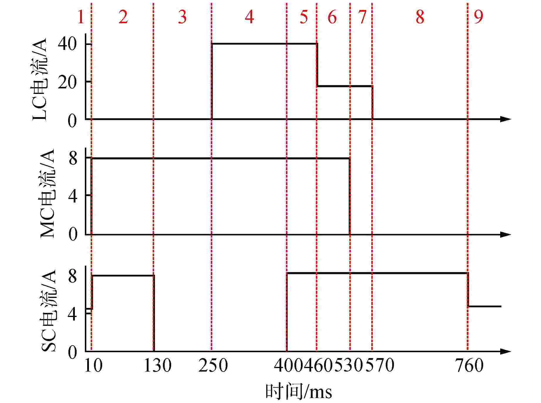
表 1 提升电流时序对应的各阶段状态
Table 1. State of Each Stage Corresponding to Lifting Current
阶段 IL/A IM/A IS/A z1/mm z2/mm z3/mm 1 0 0 4.7 15.875 8.6 0 2 0 8 8.0 15.875 0 0 3 0 8 0 15.875 0 10.2 4 40 8 0 0 0 10.2 5 40 8 8.0 0 0 0 6 16 8 8.0 0 0 0 7 16 0 8.0 0 8.6 0 8 0 0 8.0 15.875 8.6 0 9 0 0 4.7 15.875 8.6 0 IL—提升线圈电流;IM—移动线圈电流;IS—保持线圈电流;z1—提升磁极和提升衔铁的间隙(提升间隙);z2—提升衔铁和移动衔铁的间隙(移动间隙);z3—保持磁极和保持衔铁的间隙(保持间隙) 表 2 插入电流时序对应的各阶段状态
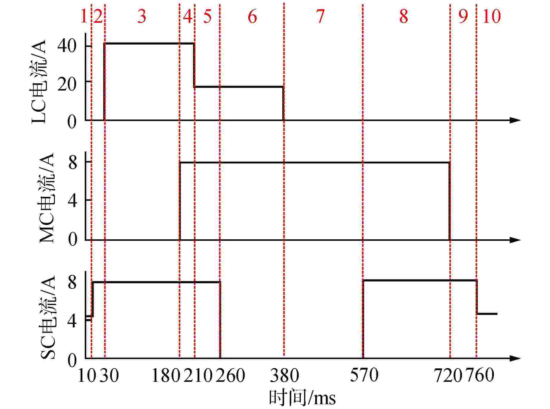
Table 2. State of Each Stage Corresponding to Inserting Current
阶段 IL/A IM/A IS/A z1/mm z2/mm z3/mm 1 0 0 4.7 15.875 8.6 0 2 0 0 8.0 15.875 8.6 0 3 40 0 8.0 0 8.6 0 4 40 8 8.0 0 0 0 5 16 8 8.0 0 0 0 6 16 8 0 0 0 10.2 7 0 8 0 15.875 0 10.2 8 0 8 8.0 15.875 0 0 9 0 0 8.0 15.875 8.6 0 10 0 0 4.7 15.875 8.6 0 表 3 控制棒驱动系统运行工况
Table 3. Operating Conditions of CDRM
工况编号 IL/A IM/A IS/A z1/mm z2/mm z3/mm 1_1 40 0 0 15.875→0 8.6 10.2 1_2 0 8 0 15.875 8.6→0 10.2 1_3 0 0 8 15.875 8.6 10.2→0 2_1 40 8 0 15.875→0 0 10.2 2_2 0 8 8 15.875 8.6→0 0 2_3 40 8 8 0 0 10.2→0 2_3_1 16 8 8 0 0 10.2→0 3_1 40 0 8 15.875→0 8.6 0 3_2 40 8 8 0 8.6→0 0 3_2_1 16 8 8 0 8.6→0 0 3_3 0 8 8 15.875 0 10.2→0 表 4 仿真参数
Table 4. Simulation Parameters
参数 数值 仿真步长/s 2×10⁻⁶ 三相交流电压峰值/V 150 三相交流电压频率/Hz 50 驱动电路斩波管开关频率/Hz 2000 -
[1] 沈小要. 控制棒驱动机构的分段非线性动态特性[J]. 中国工程机械学报,2011, 9(4): 410-415. doi: 10.3969/j.issn.1672-5581.2011.04.006 [2] 魏乔苑,张飞,吴和北,等. 控制棒驱动机构运动过程的联合数值仿真研究[J]. 核动力工程,2018, 39(5): 137-141. [3] 张知竹,刘志明,李海博,等. 磁力提升型控制棒驱动机构电磁场仿真分析[J]. 机械设计与制造工程,2019, 48(12): 33-37. doi: 10.3969/j.issn.2095-509X.2019.12.008 [4] 李孟葵. 磁力型控制棒驱动机构电磁仿真与优化设计[D]. 成都: 四川大学,2021. -


 下载:
下载:
