


Study and Prevention of Steam Flow Induced Vibration of Nuclear Power Plant Condenser
-
摘要: 针对某类型核电厂凝汽器在单列运行时发生多起因汽流激振导致的钛管开裂事件,采用基于多孔介质模型的计算流体动力学(CFD)方法对该凝汽器的喉部和管束区汽侧流场进行全三维数值仿真,计算得到凝汽器在多个单列运行工况下的汽侧速度场与钛管汽流激振风险系数分布。根据仿真计算结果,该凝汽器单列运行时,在靠近凝汽器垂直中心线的换热模块空冷区上方的指缝区表层钛管发生汽流激振的风险较高,为降低汽流激振风险需要考虑在相关位置安装防振条或实施预防性堵管。根据凝汽器单列运行泄漏工况数值仿真计算结果与核电机组实际运行记录,建议该核电厂凝汽器单列运行时在夏季、冬季工况下机组安全运行电功率限值分别为900 MW和600 MW。该凝汽器钛管跨距偏大,为了避免发生汽流激振现象,应将钛管跨距缩短到610.5 mm以下。Abstract: In view of a number of titanium tube cracking events caused by steam flow induced vibration of a certain type of nuclear power condenser under half-side condenser operation conditions, this paper uses the computational fluid dynamics (CFD) method based on porous medium model to conduct a full three-dimensional numerical simulation of the steam-side flow field in the throat and tube bundle area of the condenser and calculates and obtains the steam-side velocity field of the condenser under half-side condenser operation conditions and the steam flow induced vibration risk coefficient distribution of titanium tubes. The simulation calculation results show that the steam flow induced vibration risk of the surface titanium tube in the finger gap area above the air-cooling area of the heat exchange module close to the vertical centerline of the condenser is relatively high under half-condenser operation conditions, and it is necessary to consider installing anti-vibration bars or taking preventive tube plugging measures to reduce the steam flow induced vibration risk. According to the numerical simulation calculation results under the leakage conditons of the condenser during half-side condenser operation and the actual operation records of the nuclear power unit, it is suggested that the electric power limits for the safe operation of the nuclear power plant condenser under the half-condenser operation conditions in summer and winter should be 900 MW and 600 MW respectively. Since the span of the condenser is a bit too large, the span of titanium tube should be shortened to less than 610.5 mm so as to avoid steam flow induced vibration.
-
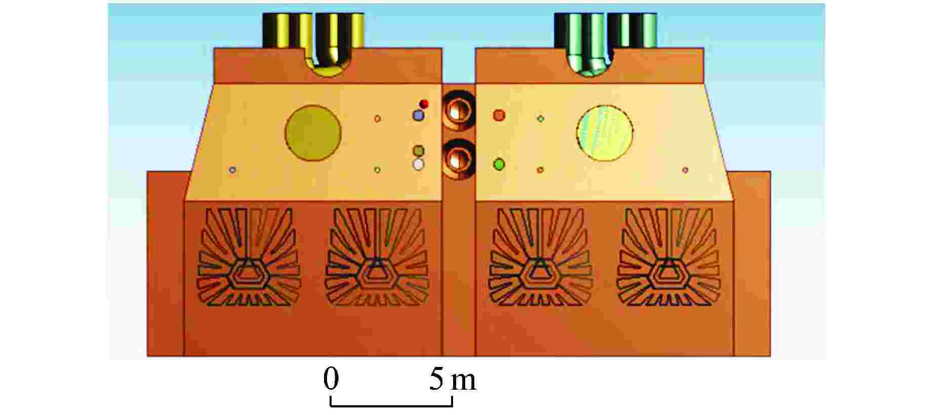
图 2 凝汽器三维模型(正视图,从进水端看)
Figure 2. Three-dimensional Model of Condenser (Front View, Viewing from Water Inlet End)
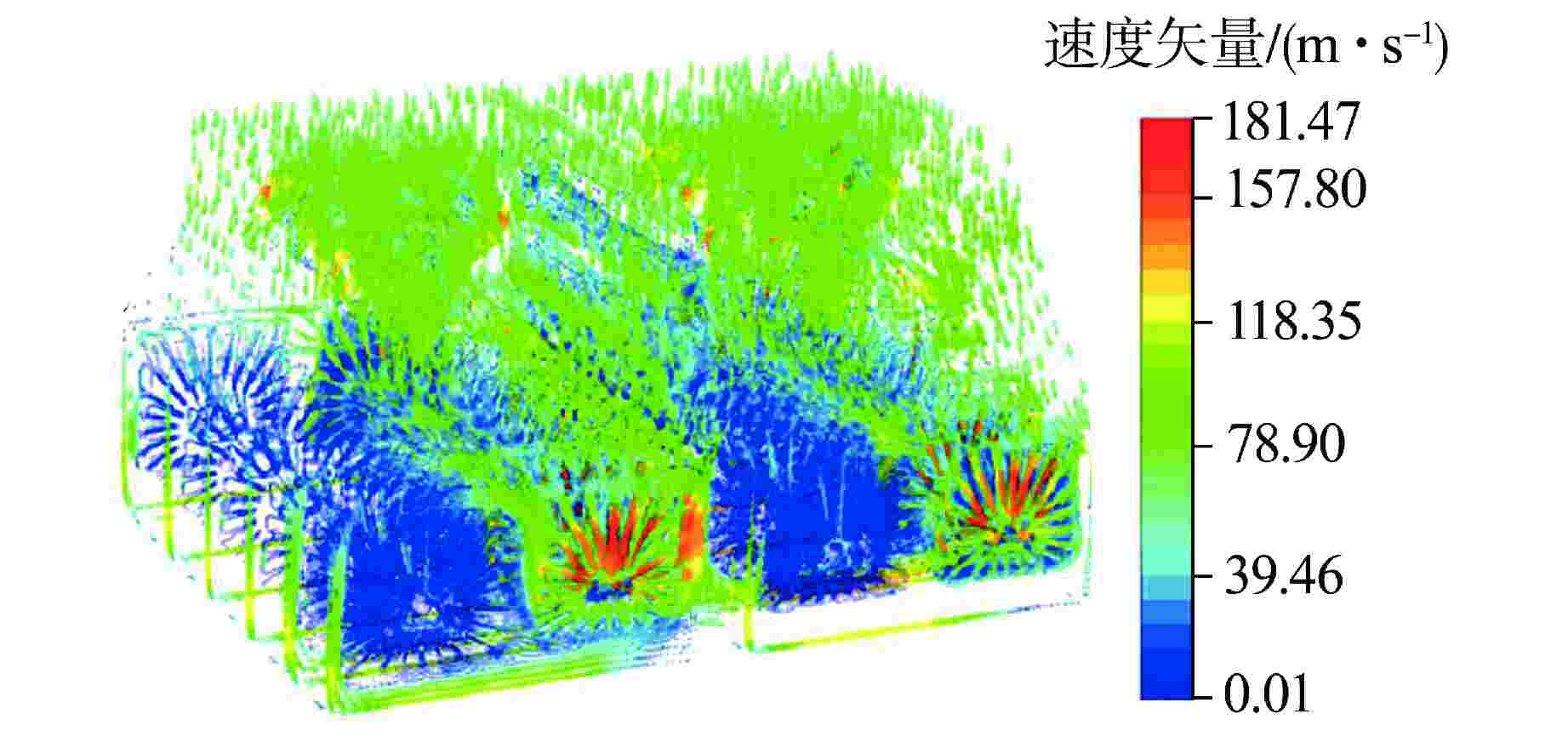
图 3 在泄漏工况Ⅰ凝汽器汽侧三维速度矢量(从进水端看)
Figure 3. Three-dimensional Velocity Vector at Steam Side of Condenser under Leakage Condition Ⅰ (Viewing from the Water Inlet End)
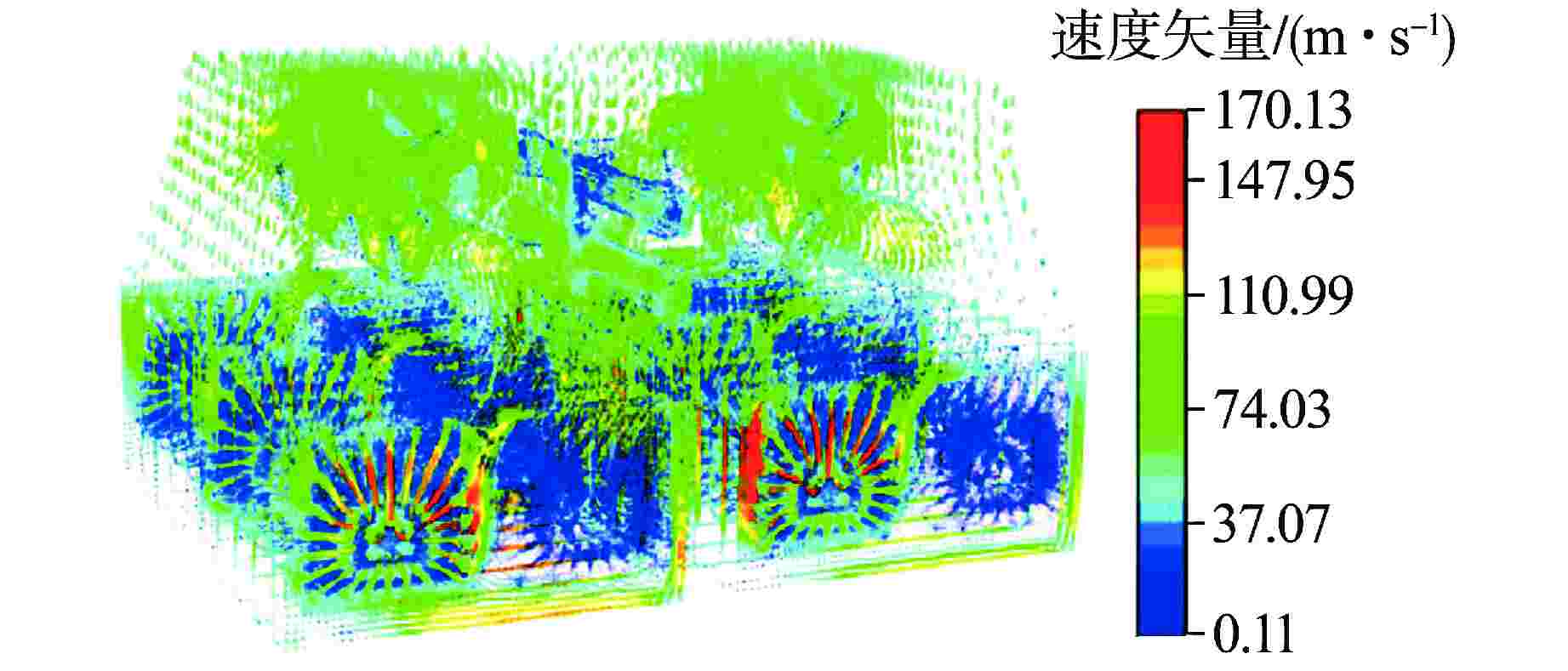
图 4 在泄漏工况Ⅱ凝汽器汽侧三维速度矢量(从进水端看)
Figure 4. Three-dimensional Velocity Vector at Steam Side of Condenser under Leakage Condition Ⅱ (Viewing from the Water Inlet End)
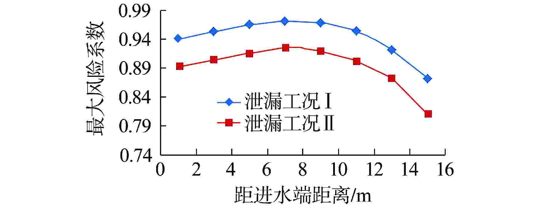
图 5 最大风险系数沿轴向的变化
Figure 5. Variation of Maximum Risk Coefficient along Axial Direction
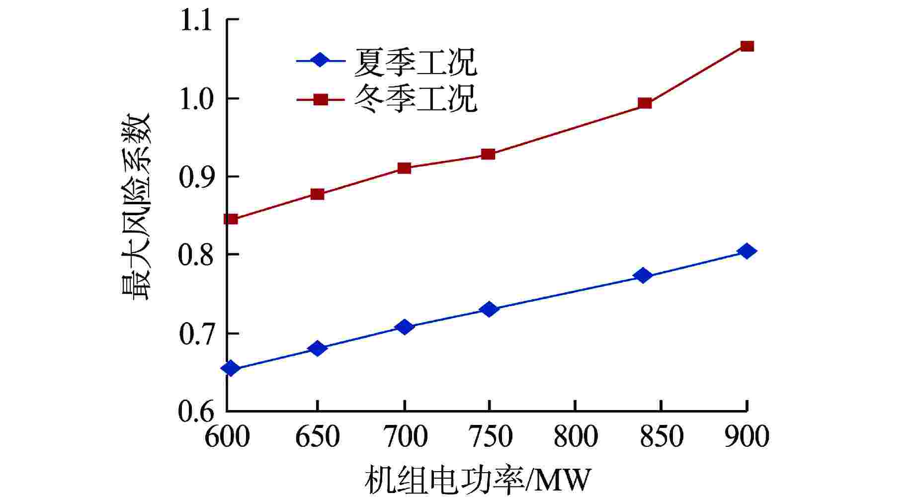
图 7 在不同工况下钛管最大风险系数
Figure 7. Maximum Risk Coefficient of Titanium Tube under Different Conditions
表 1 凝汽器泄漏事件运行参数
Table 1. Operation Parameters under Condenser Leakage Condition
项目 泄漏工况Ⅰ 泄漏工况Ⅱ 机组电功率/MW 977 833 运行列 1A/3A 2B/4B 汽轮机排汽量/(kg·s−1) 753.8 650.4 蒸汽干度 0.91 0.91 1A侧高压加热器应急疏水
闪蒸汽量 /(kg·s−1)0 22 蒸汽压力/Pa 5.8 4.7 海水温度/℃ 18.8 20.5  下载: 导出CSV
表 2 各工况下钛管风险系数
Table 2. Risk Coefficient of Titanium Tube under Various Conditions
工况 单/双列 海水温
度/℃蒸汽流量/
(kg·s−1)蒸汽比体积/
(m3·kg−1)临界流速/
(m·s−1)指缝区最高流速/
(m·s−1)钛管风险
系数要求$ \alpha K\sqrt \delta $ 钛管风险系数 厂家 TMCR 双 24 823.51 23.64 156.6 98.0 <1 0.581 0.626 100%TMCR 双 24 823.511 22.87 154.1 133.6 <1 0.581 0.867 工况Ⅰ(977 MW) 单 18.8 753.8 22.21 151.8 171.4 ≥1 0.581 1.129 工况Ⅱ(833 MW) 单 20.5 672.4 27.15 167.9 169.0 ≥1 0.581 1.007 夏季 600 MW 单 24 516.4286 19.756 143.2 108.4 <1 0.581 0.757 650 MW 单 24 554.246 18.68 139.2 109.5 <1 0.581 0.786 700 MW 单 24 590.913 17.92 136.4 112.0 <1 0.581 0.821 840 MW 单 24 690.844 15.88 128.4 114.8 <1 0.581 0.894 900 MW 单 24 735.009 15.02 124.9 115.2 <1 0.581 0.923 冬季 600 MW 单 10 483.71 37.99 198.6 194.8 <1 0.581 0.981 650 MW 单 10 519.559 35.89 193.0 195.6 ≥1 0.581 1.013 700 MW 单 10 555.124 34.01 187.9 198.3 ≥1 0.581 1.055 750 MW 单 10 591.415 31.57 181.0 195.8 ≥1 0.581 1.082 840 MW 单 10 651.000 29.51 175.0 204.0 ≥1 0.581 1.166 900 MW 单 10 693.036 27.65 169.4 222.9 ≥1 0.581 1.316
下载: 导出CSV
-
[1] 袁小会,蔡逸飞. 凝汽器钛管断裂失效分析[J]. 武汉工程大学学报,2014, 36(3): 53-57. doi: 10.3969/j.issn.1674-2869.2014.03.011 [2] 陈杰. 凝汽器换热管断裂损伤分析与综合防治[J]. 热力发电,2019, 48(6): 115-120. doi: 10.19666/j.rlfd.201901039 [3] 祖帅,车银辉,关建军,等. 核电厂凝汽器泄漏共性问题分析及防治[J]. 热力发电,2020, 49(12): 164-169. doi: 10.19666/j.rlfd.202003065 [4] 汪国山. 电站凝汽器热力性能数值仿真及其应用[M]. 北京: 中国电力出版社, 2010: 18-21, 101. [5] ZHANG C. Numerical modeling using a quasi-three-dimensional procedure for large power plant condensers[J]. Journal of Heat Transfer, 1994, 116(1): 180-188. doi: 10.1115/1.2910854 [6] AFGAN N, SPALDING D B. Turbulent Buoyant Convection or HTS Report 76/11[C]//The calculation of free-convection phenomena in gas-liquid mixtures, ICHMT Seminar Dubrovnik , Washington D C: Hemisphere, 1976: 569-586. [7] AFGAN N H, SCHLUNDER E U. Heat Exchangers: Design and Theory Sourcebook[M]. Washington D. C: Scripta Book Company,1974: 155-176. [8] CONNORS JR H J. Fluidelastic vibration of heat exchanger tube arrays[J]. Journal of Mechanical Design, 1978, 100(2): 347-353. doi: 10.1115/1.3453921 [9] PETTIGREW M J, GORMAN D J. Vibration and heat exchanger tube bundles in liquid and two-phase cross flow[J]. Proceedings of the ASME pressure vessel and piping conference, 1981, 52: 59-110. [10] 汪国山. 岭澳核电厂二期凝汽器内部三维流场仿真分析研究报告[D]. 上海: 上海交通大学, 2021. [11] 张水桃,许晔,鲁前奎. 核电汽轮机凝汽器冷却管避免振动碰磨的预防措施[J]. 东方汽轮机,2014(3): 1-4,10. doi: 10.13808/j.cnki.issn1674-9987.2014.03.001 [12] GEBCO Engineering Inc. Design and operating guidelines for nuclear power plant condensers: EPRI-NP-7382[R]. Palo Alto: EPRI, 1991. -

 下载:
下载:


计量
- 文章访问数: 358
- HTML全文浏览量: 156
- PDF下载量: 31
- 被引次数: 0
