


Multi-Objective Optimization Design of Self-sensing Rod Position Detector End Compensation Based on MOPSO Algorithm
-
摘要: 自感式棒位探测器利用探测线圈电感随驱动杆位移的变化特性实现连续棒位测量,但实际探测线圈端部磁场的非均匀分布致使探测器端部的输出信号表现为非线性,降低了端部位置的测量精度。为此,本文提出一种在探测线圈两端绕制阶梯型补偿线圈的多目标优化设计方法:①建立端部补偿线圈电感数学模型;②采用多目标粒子群优化(MOPSO)算法对补偿线圈结构进行多目标优化;③利用熵权法和模糊综合评价法对多个优化目标客观赋权并进行综合评价,选取一组折中最优设计方案,从而快速有效地确定补偿线圈的最优结构参数。通过有限元仿真对比补偿前后结果,发现经过端部补偿后,不仅电感灵敏度提高了28.6%,最大线性拟合误差也降低了45.8%;最后,进行样机实验,结果显示端部补偿后的探测线圈电感灵敏度为0.18 mH/10 mm,最大线性拟合误差小于0.18 mH,可实现10 mm的测量精度,验证了端部补偿线圈多目标优化设计方案的有效性。本文为其在模块化小型反应堆中的应用提供了优化设计理论基础。
-
关键词:
- 反应堆 /
- 自感式棒位探测器 /
- 端部补偿 /
- 多目标粒子群优化(MOPSO) /
- 多目标优化
Abstract: The self-sensing rod position detector utilizes the variation characteristics of the detecting coil inductance with the rod displacement to achieve continuous rod position measurement. However, the non-uniform magnetic field distribution at the coil ends leads to a nonlinear output signal, reducing the measurement accuracy at both ends. Therefore, this paper proposes a multi-objective optimization design method for winding stepped compensating coils at both ends of the detecting coils: ① Develop a mathematical model for the inductance of the end compensation coils; ② Adopt a multi-objective particle swarm optimization (MOPSO) algorithm for the optimization of the compensation coil structure; ③ Employ the entropy weight method and fuzzy comprehensive evaluation to assign weights to multiple optimization objectives and select a compromise optimal design, thereby efficiently selecting the optimal structural parameters of the compensation coils. By comparing the results before and after compensation through finite element simulation, it was found that the end compensation improved inductance sensitivity by 28.6% and reduced the maximum linear fitting error by 45.8%. Finally, prototype experiments were conducted, which indicated that the inductance sensitivity of the end-compensated detection coil is 0.18 mH/10 mm, with a maximum linear fitting error under 0.18 mH. These results confirm a measurement accuracy of 10 mm and validate the effectiveness of the multi-objective optimization design for the coil. This study provides a theoretical foundation for the optimization of its application in modular small reactor design. -
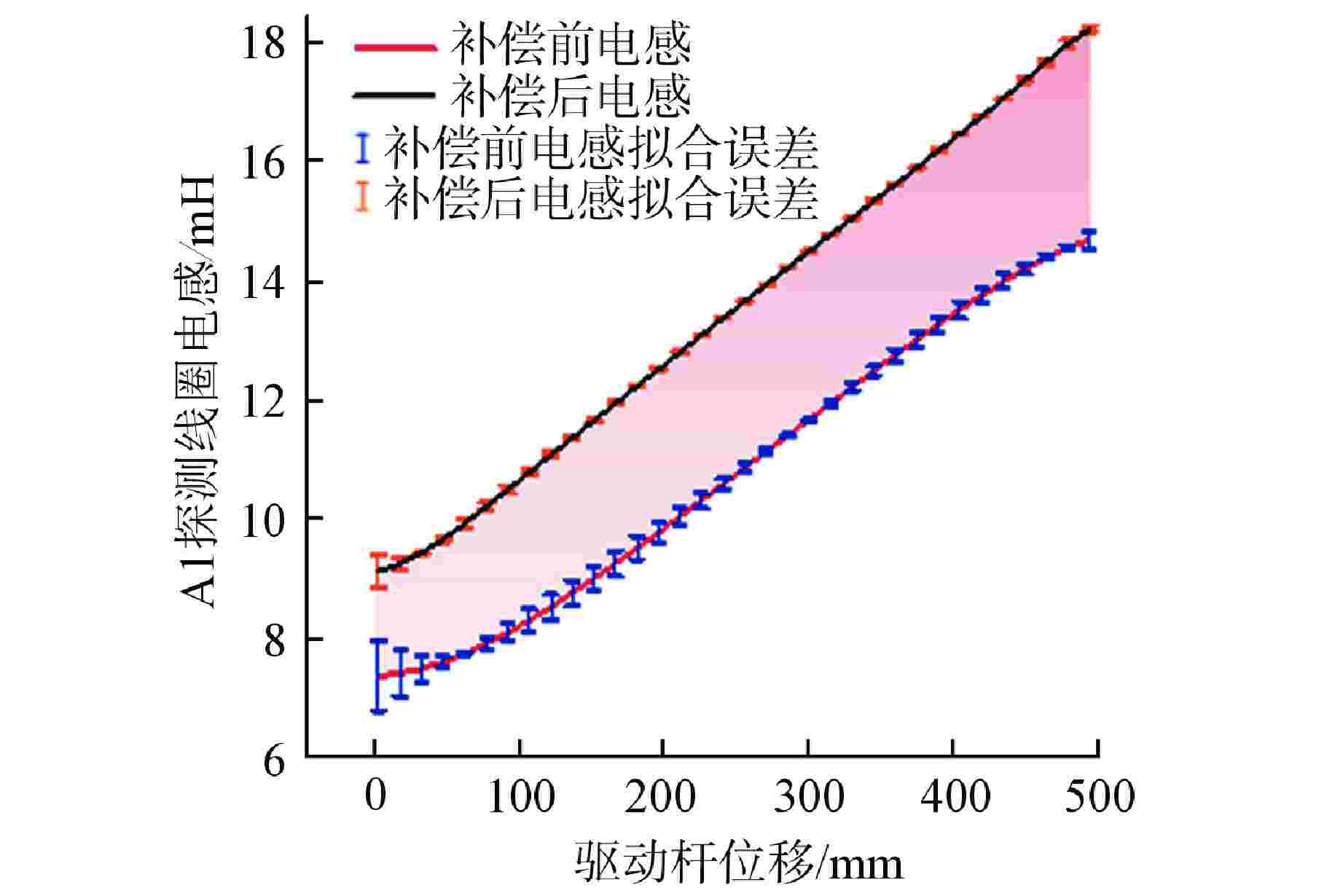
图 9 补偿前后线圈电感及线性拟合误差
Figure 9. Inductance and Linear Fitting Error Comparison before and after Compensation
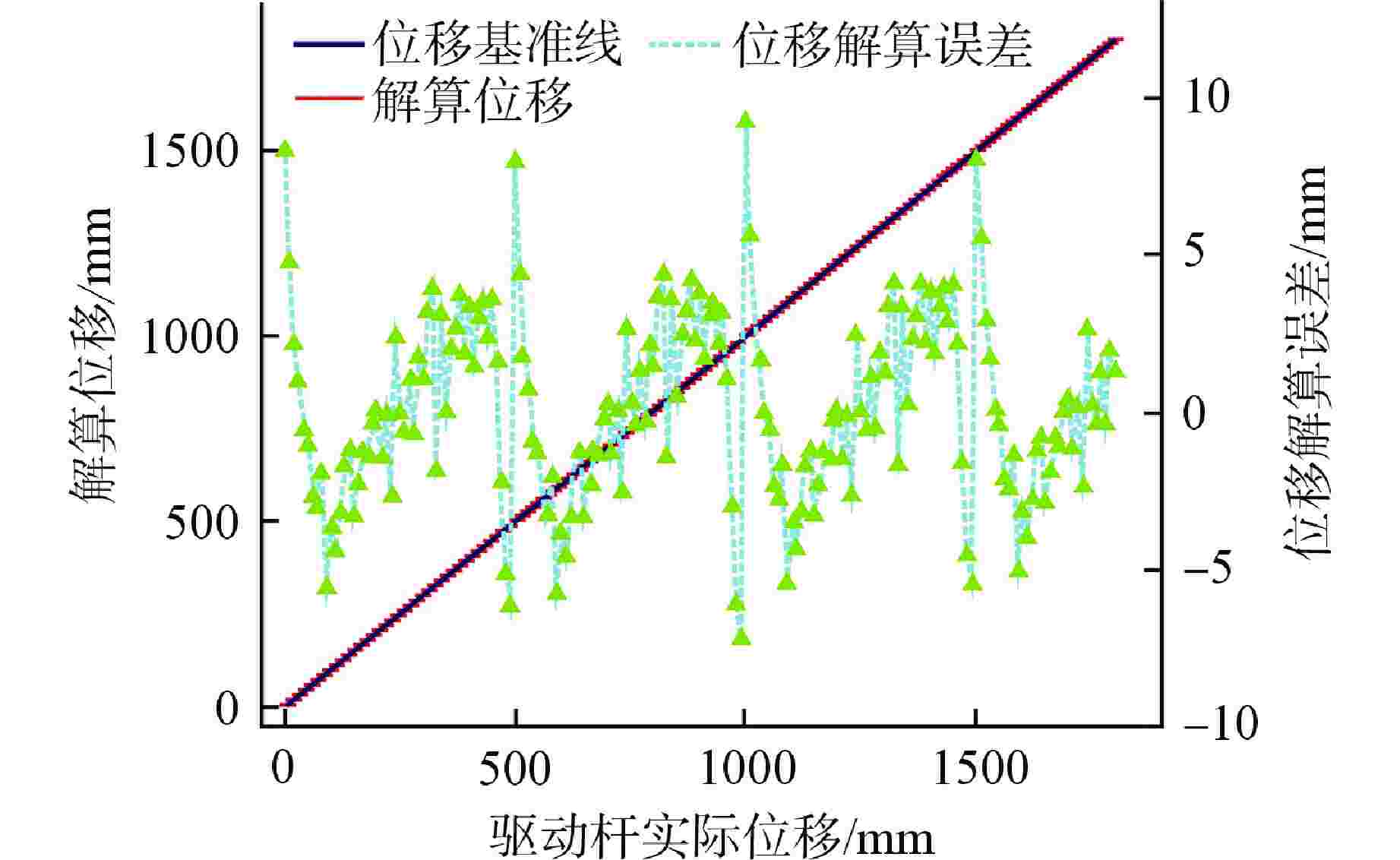
图 13 驱动杆的实际位移和解算位移
Figure 13. Comparison of Actual Displacement and Calculated Displacement of the Rod
表 1 棒位探测器固定参数
Table 1. Fixed Parameters of the Rod Position Detector
参数名 参数值 探测线圈总长/mm 1995 线圈分段/段 4 线圈内径/mm 119 单段线圈长度/mm 495 线圈线径/mm 1.4 单段A组线圈匝数/匝 180 探测线圈层数/层 3 端部补偿线圈层数/层 3 相邻线圈间隔/mm 5 驱动杆半径/mm 22.25 驱动杆长度/mm 2500 激励电流幅值/A 0.1 激励频率/Hz 200  下载: 导出CSV
表 2 最优折中设计方案
Table 2. Optimal Compromise Design
设计变量 C11 C12 C13 C21 C22 C22 补偿线圈第一层匝数/
匝14 13 11 12 11 9
下载: 导出CSV
表 3 补偿前后结果对比
Table 3. Comparison before and after Compensation
目标 优化前 优化后 电感灵敏度/(10−1mH·mm−1) 0.14 0.18 最大线性拟合误差/mH 0.59 0.32 平均线性拟合误差/mH 0.145 0.037 电感变化量/mH 7.31 9.09 补偿线圈第一层匝数/匝 0 26
下载: 导出CSV
表 4 探测线圈测量电感拟合结果
Table 4. Linear Fitting Results of Measured Inductance
子线圈序号 电感灵敏度/(10−1mH·mm−1) 最大线性拟合误差/mH A1 0.182 0.156 A2 0.181 0.162 A3 0.181 0.163 A4 0.182 0.160
下载: 导出CSV
-
[1] 王兴,高鸣,黄尧. 压水堆核电站棒位测量偏差分析及应对[J]. 电子技术应用,2022, 48(S1): 5-8. [2] 堵树宏,李永华,孙涛,等. 微型核反应堆技术发展趋势研究[J]. 核动力工程,2022, 43(4): 1-4. [3] 于天达,吴昊,陈西南,等. 核反应堆控制棒驱动机构用棒位探测器及其使用方法: 中国,112071456A[P]. 2020-12-11. [4] HU G, ZHANG H, LIU Q F. Review on sensors to measure control rod position for nuclear reactor[J]. Annals of Nuclear Energy, 2020, 144: 107485. doi: 10.1016/j.anucene.2020.107485 [5] 李德重,王文然,杨念祖,等. 自编码数字式控制棒位置测量指示系统[J]. 核动力工程,1996, 17(3): 209-212,229. [6] 王文然,蒋跃元,卫亚力. 软件补偿自编码棒位指示系统[J]. 核动力工程,1999, 20(2): 124-129. [7] 赵亮. 核电站反应堆无补偿线圈棒位测量系统设计与研究[D]. 衡阳: 南华大学,2012. [8] BAEK M H, HONG H B, PARK H J. High precision solenoid type nuclear reactor control rod position indicator[J]. The Transactions of the Korean Institute of Electrical Engineers, 2016, 65(11): 1848-1853. [9] 潘惠龙. 核电站用新型高精度棒位探测器电磁耦合机理及棒位解算策略研究[D]. 重庆: 重庆大学,2022. [10] 张艺璇,徐奇伟,唐健凯,等. 反应堆用新型自感式棒位探测器涡流效应分析[J]. 核动力工程,2024, 45(1): 156-163. -

 下载:
下载:


计量
- 文章访问数: 179
- HTML全文浏览量: 58
- PDF下载量: 16
- 被引次数: 0
